

In this article we will document the manufacture of an watch using digital manufacturing techniques.
The Carbon-Fibre Biscuit-Watch:

Our stated aim is to demonstrate my methods in digital manufacturing to deliver a consumer product on par with products on sale in stores. The motivation is rooted in a previous article Full 3D Metal (Jacket) Printing @HOME where I stated the following:
“3D Printing is revolutionising manufacturing, but 3D printing at HOME is still a novelty. Department stores now have low-end 3D printers in their PC electronics departments, yet their usefulness for making real “stuff” is debatable. Certainly these printers do not render the type of things we, ourselves, tend to buy in same said stores.
I would like to challenge that.”
So I chose the most challenging, intricate consumer product I could think of: watches. Why? Here is from Otto Frei, a leading supplier of watch parts:

I have never disassembled a watch, never made one, so here was a good challenge. I purchased a movement…and made sure it was the most delicate I could think of: kinetic, self-winding, 27 jewels.
Citizen Self-Winding Movement:

The rest if this blog will be devoted to showing the stages of creation of the watch.
Material Accounting: All materials and parts have been sourced from Australia, the United States, the United Kingdom, Japan and Switzerland.
Capabilities Accounting: In order to manufacture our watch, we require at a minimum: one 3D printer modified to print carbon fiber. I used a modified Lulzbot Taz 5 manufactured in the United States. Optional and dependent on choice of materials: a CNC laser cutter, a jewellery tumbler, a kiln to sinter 3D printed metal, and a digitally programmable toaster oven.
Besides demonstrating my methods, what we aim to demonstrate is that all of the value added comes from two sources: 1) human creativity in the form of modelling 2) digital capabilities that can be fielded via computing and optionally “robotics.” The ideology embodied here is reminiscent of the Maker Culture that has gained popularity across the world, but adds enabling “digital sauce” that removes 1) reliance on dedicated Maker Spaces and 2) allows creators to manufacture end-to-end usable consumer goods that are worthy of point-of-sale. Crucially, there is no principle reliance on tier-1 manufacturers to arrive at point-of-sale. This has the potential to enable many smaller firms and one-man enterprises.
The Carbon-Fibre Biscuit-Watch:

Why call this the “Carbon Fiber Biscuit Watch?” I have a long-held fascination with biscuit tins, old and new alike. After much deliberation, the watch face was cut from the Walkers biscuit tin shown below.
The Biscuit Tin:

The watch itself is made from fiber composites: carbon fiber (black) and plant-fibre reinforced annealed polymer (white). I didn’t want “just” plastic. I wanted something so tough, you can boil it and it will keep its shape. The back of the watch features a transparent backing plate that permits a view on the movement contained within.
Made in Australia – Rotating Kangaroo:

The weight of a kinetic movement rotates to wind the watch spring — which became a rotating kangaroo. Also visible here is the waterproofing seal. The entire watch is made to close enough tolerances so as to be waterproof — I don’t have the equipment to test to what precise depth.
Optionally, the watch bezel and or its other parts can be made from 3D printed metal. Shown below is a 3D printed copper bezel prior to finishing. I use filament from the Virtual Foundry, in Stoughton Wisconsin, U.S.
Copper Bezel:

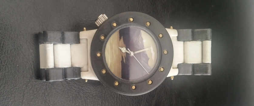
To add a romantic touch, I have made two of these: one for my wife and one for myself, both cut from one and the same biscuit tin so as to create a perfect partner style. I called the lady’s model the “Baby Biscuit Watch.”
Baby Biscuit Watch:

The Baby Biscuit Watch was particularly challenging, due to size constraints, about the size of a United States Dime. It was also my first watch ever.
How is it done?
Shown below is the digital model of the watch case. The model is created in Guile Scheme, a derivative of the language Lisp. Other languages and models are possible, but Scheme was chosen for its ability to accommodate higher order, functional abstractions. This is important as we will be generating models from specifications. We want the ability to not merely perform function on data (naive first order logic, Python, C++) but crucially we want the ability to compute, rewrite and optimise “function” itself. “Function” that computes “function” is higher order logic. My development environment is simply Emacs where I have set up a dedicated “Live Coding” environment similar to the lib five project.
The CAD library used here is based on Antimony by MIT’s Center for Bits and Atoms. The programmatic version of Antimony is called AO which has now been absorbed into the lib five project.
AO Scheme Model Specification – 3D Printed

The Virtual Drill
Many of the manufacturing steps embodied in traditional manufacturing are reduced to suitable constructs in Lambda Calculus. Shown below is our definition of “drill holes” referenced above.

Oriented Differencing
Worth noting is that both additive and subtractive manufacturing steps are embodied in our models. Subtractive steps are expressed as omissions in the model. As it turns out, this is a very powerful technique for creating moulded parts matched to other parts. For example, creating a watch strap moulded to fit our watch case is simply expressed as: moulded strap = original strap – watch. First the plain parts:


In the above setting, model and strap are “unoriented,” which is to say they are not positioned as intended when assembled. To create a moulded strap, we orient both model and strap, then “difference” them.


Now remove the watch case and what is left is a custom “moulded” strap:


Repeated “differencing” at different angles of rotation yields a part that is designed to pivot against another within specific degrees of freedom.
Stage 1 – The Case
The case will hold the watch movement, receive the bezel that holds the watch crystal, and connect to the watch straps. It must also have a tube to hold the crown to allow the time to be set on the movement. Overall sizing must consider natural curvature of the human wrist. We define various style options, square, triangular and the traditional round case.
Because the watch face shows a motive from the biscuit tin, I had two choices: a) leave out the hour and minute markers so as to not obstruct view onto the watch face motive or b) move the hour and minute markers onto the bezel. I opted for the latter, eliding the minute markers. Simultaneously, the hour markers serve to hold bezel, case and backing plate together.
We define the following Form Factors:

This produced the following cases:


The digital models are exported to STL files and rendered in a 3D printer. We can render our models using different materials, here: 3D printed copper.
Copper Case – Prior to Sintering or Surface Finish:


Material science is an intricate and complex subject. Shown below is a full carbon fiber body with a 3D printed copper watch face. I would later abandon this design, but it was interesting to explore if I could 3D print copper to small enough tolerances to fit the watch hands. As it turns out, I could. (The stem provides approximately 0.4 mm clearance between movement and hour hand) 3D printing metal to close tolerances is still a bit of an art.
Carbon Fiber Body and Copper Watch Face:

Carbon Fiber Body and Copper Watch Face
The watch case also accommodates the screw-on crown stem.

We are now ready to place the movement and add the face:

Now we place and align the watch bezel. Note how the bezel has as yet an unfinished somewhat textured surface resulting from both the fibrous texture of the material as well as the 3D printing process. Also, fitted is the watch crown.
Align Carbon Fiber Bezel – Crown Fitted:

Additionally, we have male and female styles – which mainly affect sizing and the angles of flanges to the casing body.

Stage 2 – The Band
As with the watch form factor, different band styles were created. The first style isn’t really a watch band at all, but allows reconfiguring the lady’s watch into a pendant on a necklace.

The lady’s watch shown at the beginning of the article, was created with the help of a leather adaptor, a small abutment with a slot that receives the leather strap. As both abutments are the same, modelling just one is sufficient.

The male styled watch comes with two band styles: a) a moulded, fitted band that we saw earlier which is designed to be printed from flexible, rubber like, filament, and b) a band made of links. Shown below is the watch case with moulded bands of flexible filament.

As for the variant of the watch band with links, because links repeat, only one of each has to be modelled. Links are designed to be joined simply by press fitting carbon fiber filament through the holes. Hole sizes have tolerances so as to provide movement in the centre link.

As with the leather strap, we need an abutment to connect the links to the watch case.

Given the above designs, we are missing but a clasp.
Stage 3 – The Clasp
The clasp is the last major piece of the puzzle. It consists of three layers, joined at hinges and a centered retainer that secures the bottom layer to the top layer when in the closed position.


The printed, assembled clasp is shown below.


Stage 4 – Final Assembly

We have glossed over many details. Many ready-made configuration options have been shown. Each can be rendered as easily as any other. Unfinished surfaces became finished surfaces. Fiber polymers became annealed. What about the kiln and the digital toaster oven? Watch bezels received watch crystals. Watch band links have been assembled. We have shown little of the source code that makes up the digital designs that we have shown. And how do product specifications become digital designs?
This and more will be subject of part 2 of this article. What we want to summarise is this: someone with no watchmaking experience has been able to fashion a watch that appears like any article on the shelves of a department store. The watch is functional, waterproof & keeps exact time. We discovered complexity, mostly in the domain of material science – yet we managed that complexity rather than succumb to that it. We also produced digital specifications that may be generated programmatically — by a system as yet to be introduced.

2 comments on “Digitally Assisted Micro-Fabrication of Consumer Grade Goods”
ฝาก 50 รับ100 ทำยอด 500 ถอนได้ 500
Good post! We will be linking to this particularly great post on our site. Keep up the great writing
Aniyah Ava Ariana Huber
Keep up the amazing work!